- 您现在的位置:买卖IC网 > Sheet目录310 > AOZ1083CI (Alpha & Omega Semiconductor Inc)IC LED DRVR BUCK CC 1.2A SOT23-6
AOZ1083
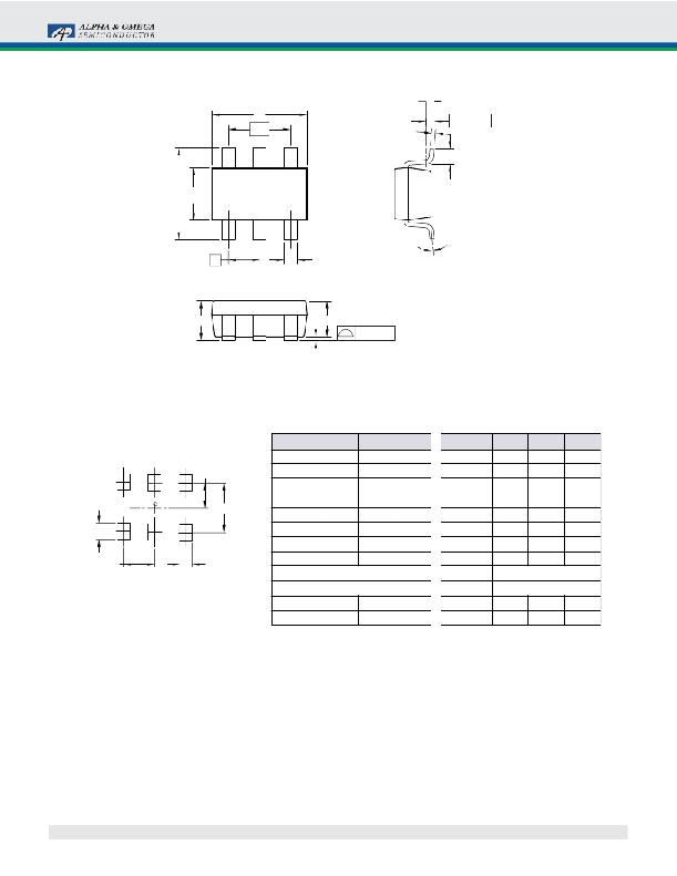
Package Dimensions, SOT23-6
Gauge Plane
Seating Plane
D
e1
c
0.25mm
L
E E1
θ 1
A
e
b
A1
A2
.010mm
Dimensions in millimeters
Dimensions in inches
RECOMMENDED LAND PATTERN
1.20
2.40
0.80
Symbols
A
A1
A2
b
c
D
E
Min.
0.90
0.00
0.70
0.30
0.08
2.70
2.50
Nom.
—
—
1.10
0.40
0.13
2.90
2.80
Max.
1.25
0.15
1.20
0.50
0.20
3.10
3.10
Symbols
A
A1
A2
b
c
D
E
Min.
0.035
0.00
0.028
0.012
0.003
0.106
0.098
Nom.
—
—
0.043
0.016
0.005
0.114
0.110
Max.
0.049
0.006
0.047
0.020
0.008
0.122
0.122
0.95
0.63
E1
1.50
1.60
1.70
E1
0.059
0.063
0.067
e
0.95 BSC
e
0.037 BSC
UNIT: mm
e1
1.90 BSC
e1
0.075 BSC
L
θ 1
0.30
0°
—
—
0.60
8°
L
θ 1
0.012
0°
—
—
0.024
8°
Notes:
1. Package body sizes exclude mold flash and gate burrs. Mold flash at the non-lead sides should be less than 5 mils each.
2. Dimension “L” is measured in gauge plane.
3. Tolerance ±0.100 mm (4 mil) unless otherwise specified.
4. Followed from JEDEC MO-178C & MO-193C.
5. Controlling dimension is millimeter. Converted inch dimensions are not necessarily exact.
Rev. 1.0 July 2011
www.aosmd.com
Page 10 of 12
发布紧急采购,3分钟左右您将得到回复。
相关PDF资料
AOZ1935QI
IC LED DRVR WHITE BCKLGT 16QFN
AOZ1977AI
IC LED DRVR BCKLGT 16SOIC
AP-104-NT
12V PLUG TRANSFORMER EMPTY CASE
AP-120
PLUG AUTO LOCKING BLACK
AP-121
PLUG AUTO LOCKING BLACK W/LED
AP-124
12V AUTO PLUG STD EURO CE
AP-129
PLUG 12V AUTO EURO CE
AP-130
PLUG 12V AUTO LED SW FUSE CE
相关代理商/技术参数
AOZ1084DI
制造商:Alpha & Omega Semiconductor 功能描述:IC LED DRVR BUCK CC 1.2A 8DFN
AOZ1092DI
功能描述:IC REG BUCK ADJ 3A 8DFN RoHS:是 类别:集成电路 (IC) >> PMIC - 稳压器 - DC DC 开关稳压器 系列:EZBuck™ 产品培训模块:Lead (SnPb) Finish for COTS
Obsolescence Mitigation Program 标准包装:50 系列:- 类型:升压(升压) 输出类型:两者兼有 输出数:1 输出电压:5V,2 V ~ 16.5 V 输入电压:2 V ~ 16.5 V PWM 型:- 频率 - 开关:45kHz 电流 - 输出:50mA 同步整流器:无 工作温度:0°C ~ 70°C 安装类型:通孔 封装/外壳:8-DIP(0.300",7.62mm) 包装:管件 供应商设备封装:8-PDIP
AOZ1094AI
功能描述:IC REG BUCK ADJ 5A SO-8 RoHS:是 类别:集成电路 (IC) >> PMIC - 稳压器 - DC DC 开关稳压器 系列:EZBuck™ 产品培训模块:Lead (SnPb) Finish for COTS
Obsolescence Mitigation Program 标准包装:50 系列:- 类型:升压(升压) 输出类型:两者兼有 输出数:1 输出电压:5V,2 V ~ 16.5 V 输入电压:2 V ~ 16.5 V PWM 型:- 频率 - 开关:45kHz 电流 - 输出:50mA 同步整流器:无 工作温度:0°C ~ 70°C 安装类型:通孔 封装/外壳:8-DIP(0.300",7.62mm) 包装:管件 供应商设备封装:8-PDIP
AOZ1094AIL
制造商:Alpha & Omega Semiconductor 功能描述:
AOZ1094AIL_2
功能描述:IC REG BUCK 8SOIC 制造商:alpha & omega semiconductor inc. 系列:EZBuck?? 包装:带卷(TR) 零件状态:停產 功能:降压 输出配置:正 拓扑:降压 输出类型:可调式 输出数:1 电压 - 输入(最小值):4.5V 电压 - 输入(最大值):16V 电压 - 输出(最小值/固定):0.8V 电压 - 输出(最大值):16V 电流 - 输出:5A 频率 - 开关:500kHz 同步整流器:无 工作温度:-40°C ~ 85°C(TA) 安装类型:表面贴装 封装/外壳:8-SOIC(0.154",3.90mm 宽) 供应商器件封装:8-SO 标准包装:3,000
AOZ1094DI
功能描述:IC REG BUCK ADJ 5A 8DFN RoHS:是 类别:集成电路 (IC) >> PMIC - 稳压器 - DC DC 开关稳压器 系列:EZBuck™ 产品培训模块:Lead (SnPb) Finish for COTS
Obsolescence Mitigation Program 标准包装:50 系列:- 类型:升压(升压) 输出类型:两者兼有 输出数:1 输出电压:5V,2 V ~ 16.5 V 输入电压:2 V ~ 16.5 V PWM 型:- 频率 - 开关:45kHz 电流 - 输出:50mA 同步整流器:无 工作温度:0°C ~ 70°C 安装类型:通孔 封装/外壳:8-DIP(0.300",7.62mm) 包装:管件 供应商设备封装:8-PDIP
AOZ1094DIL
制造商:Alpha & Omega Semiconductor 功能描述:Conv DC-DC Single Step Down 4.5V to 16V 8-Pin DFN EP T/R 制造商:Alpha & Omega Semiconductor 功能描述:IC REG BUCK ADJ 5A 8DFN
AOZ1110
制造商:AOSMD 制造商全称:Alpha & Omega Semiconductors 功能描述:4A Synchronous EZBuck Regulator
